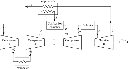
regenerative gas turbine engine diagram
Use Of Drain Cooler In Power Plant - Best Drain Photos Primagem.Org. 9 Pictures about Use Of Drain Cooler In Power Plant - Best Drain Photos Primagem.Org : Definition of The Intercooling, Reheat, Regenerative Gas-turbine Cycle, Definition of The Intercooling, Reheat, Regenerative Gas-turbine Cycle and also Schematic diagram of the Stirling heat engine cycle | Download.
Use Of Drain Cooler In Power Plant - Best Drain Photos Primagem.Org
 www.primagem.org
Definition Of The Intercooling, Reheat, Regenerative Gas-turbine Cycle
 www.chegg.com
turbine gas intercooling cycle reheat regenerative diagram regeneration reheating stage ideal figure
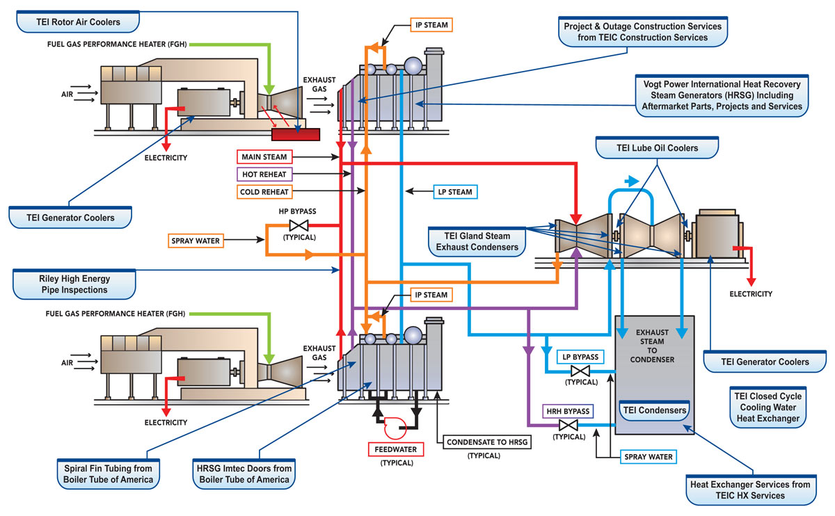
Solved: A Schematic Of A Combined Gas-steam Cycle Power Pl... | Chegg.com
 www.chegg.com
solved gas cycle steam combined schematic power problem been
Schematic Diagram Of The Stirling Heat Engine Cycle | Download
 www.researchgate.net
stirling
Schematic Diagram Of RSCBC/ORC Dual-loop Cycle. | Download Scientific
 www.researchgate.net
rankine brayton theoretical regenerative supercritical
2. Performance Map Of Holset HX80 Turbocharger. The Solid Circles
 www.researchgate.net
holset hx80 turbocharger circles indicate
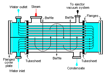
Thermal Power Plant: Steam Turbine Driven Electric Generator
 thermal-powerplant.blogspot.com
steam turbine condenser generator driven heat cooling exchanger water tube surface thermal plant condensing electric power liquid exhaust powerplant
Definition Of The Intercooling, Reheat, Regenerative Gas-turbine Cycle
 www.chegg.com
turbine gas intercooling regenerative reheat cycle regeneration reheating
Gas Turbine Engine Market – Global Gas Turbine Engine Industry Size,
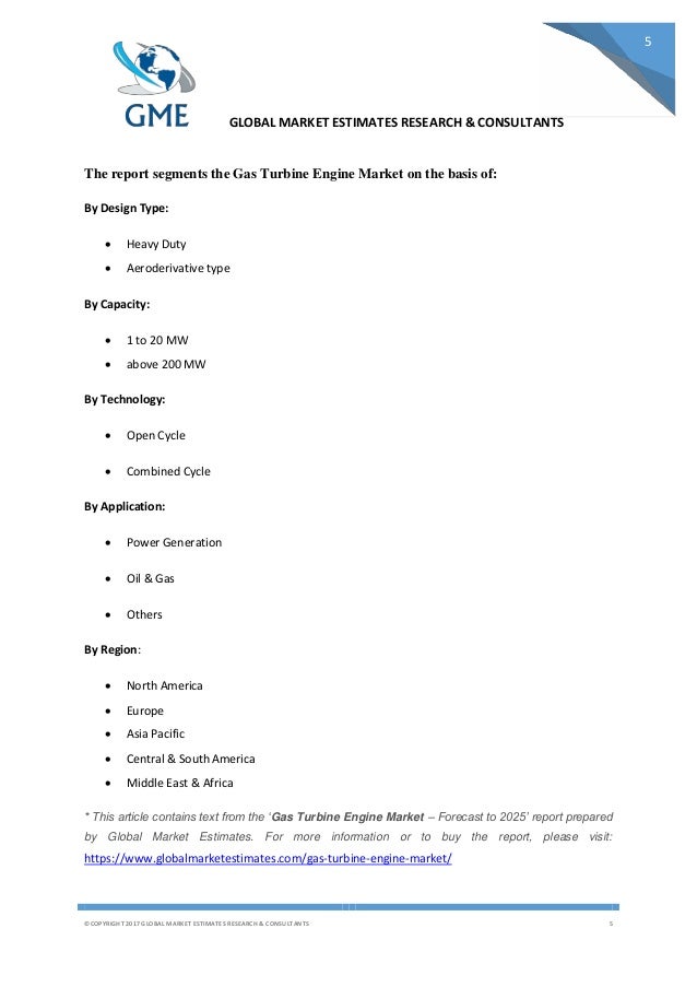 www.slideshare.net
Definition of the intercooling, reheat, regenerative gas-turbine cycle. Solved gas cycle steam combined schematic power problem been. 2. performance map of holset hx80 turbocharger. the solid circles